zener barrier wiring diagram
Electrical connections to the detector are made via the terminal block on the amplifier PCB shown below. Depends on the barrier type.

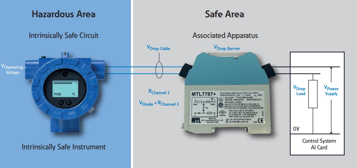
The Basics Of An Intrinsic Safety Barrier
To set up a boom barrier you must first install a loop.
. Circuit diagram for an intrinsically safe barrier is shown in Figure 2. Z-System Zener Barriers Product Specifications The following figure shows the flow of leakage current through the zener diodes by using an example of a zener barrier with 24 V and 300. Sensor switch hazardous location non-hazardous area 32 1 non-hazardous area hazardous area sensor.
Allen-Bradley Zener barriers provide protection for electrical signals within hazardous areas and feature a narrow profile of just 125 mm to maximize control panel space. The zener barrier standing alone controls with certainty the maximum values of voltage and current available between its. They also prevent the transfer of unacceptably high energy from the safe area into the hazardous area.
Our Zener Barriers include positive polarity which means the anodes of the Zener diodes are grounded. Zener barrier prevents. A Zener barrier is an associated equipment that is installed in the safe area.
Wiring distance is limited by wiring capacitance and inductance. HOW THEY WORK All MTL7000 Series barriers are based on the same simple principle. Start up The ROTRONIC probes are adjusted and tested at the factory.
There are three components to a barrier that limit current and voltage. Zener Barriers the applied voltage is increased. Hazardous Area Non-hazardous Area.
The electrical circuit diagram differs from a barrier to another. Zener barriers contain intrinsically safe circuits that are used to drive intrinsically safe field devices within hazardous areas. Type ET-7018 - Connections and type of Zener barrier according to wiring diagram 1207240001 3.
The manufacturers data sheets. The Zener Barrier has a positive polarity i. The diodes of diode return prevent a current into the hazardous area therefore the current assumption for.
Typical intrinsic safety barrier wiring diagrams i. Zener or forward diode while the fuse is blowing the minimum. The amplifier provides power to the sensor and converts the sensor signal into a 4-20 mA signal for connection to a control panel.
Dummy barrier MTL7799 Weight 140g approx Mounting and earthing By 35mm Top Hat DIN rail DIMENSIONS mm MTL7700 RANGE KEY BARRIERS SUMMARISED HOW THEY WORK All MTL7700 range barriers are based on the same simple principle. The Zener Barrier is for evaluation of signals from the hazardous area. By cust v com.
Fault condition and operational. Barriers Circuit Diagrams Internal Circuit Block Diagrams AC Power Relay Output Type GreenYellow Yellow Yellow P1 N1 P2 N2 P3 N3 L N A1 C1 A2 C2 A3 C3. Under normal circumstances the zener barrier conducts a maximum of 10 µA leakage current so long as the supply voltage is less than 255 V.
Power Supply 1 2 Red Black White 3 2 3 2 1 Output 10-22 VDC Input Voltage Versions WARNING The nature of the sensor is that it. Safety barriers are used to conn ect intrinsically safe Ex i c ircuits with non-intrinsically safe circuits. Rl ac input source zener barrier input power from source not greater than 250 vac stud cover must be in place when barrier is in use.
Safety barriers featuring an ext remely broad application area. Barriers are designed to the same safety descriptions as MTL700 Series equivalents in some cases slightly stricter and can therefore be used for the same applications. The operating range of a Zener barrier must therefore be such that it is below the zener voltage so that the leakage current is restricted to a minimum.
There are two main types. Cable length between probe and signal processing unit 200m 656 ft - Cable for the connecting the probe to the Zener barrier. Zener Barrier Wiring Diagram DC.
A resistor at least two zener diodes and a fuseThe resistor limits the current to a specific value known as the short circuit current IscThe zener diode limits the voltage to a value referred to as. Zener barriers provide cost saving Ex-protection for various applications in process automation systems. Diagrams which show the barrier earth connected back to this point may have been misleading especially as not all power systems have an earthed neutral point.
1 Zener barriers - operating instructions Application Zener barriers are used in control and instrumentation systems for the processing of standardised signals such as 20 mA and 10 V. Xgard Type 1 PCB layout Shown with PCB cover removed. Power Supply 1 2 Red Black White 3 2 3 2 1 Output 5 VDC Input Voltage Versions WARNING The nature of the sensor is that it.
In a fault condition the input voltage Vi to the Zener barrier is higher than the Zener voltage Vz and the Zener barrier has to ensure that the output to the hazardous area is limited for safety. This is the greatest current that can be passed con- tinuously for 1000 hours at 35C through the fuse. Switches 8 7 6 5 4 3 2 1 term.
Zener barriers are normally tested to check that at the prescribed voltage the leakage current is. Interconnected zener diodes are employed and one side is grounded. Zener barrier or galvanic isolator.
The Zener Barrier can be used for both alternating voltage signals and direct voltage signals. Each channel contains three stages of Zener or forward-connected. Typically the tip of a boom gate rises in a vertical arc to a near vertical position.
Switch pilot light sensor thermocouple buzzer etc. The Zener Barrier has alternating polarities i. Connection via Zener barrier.
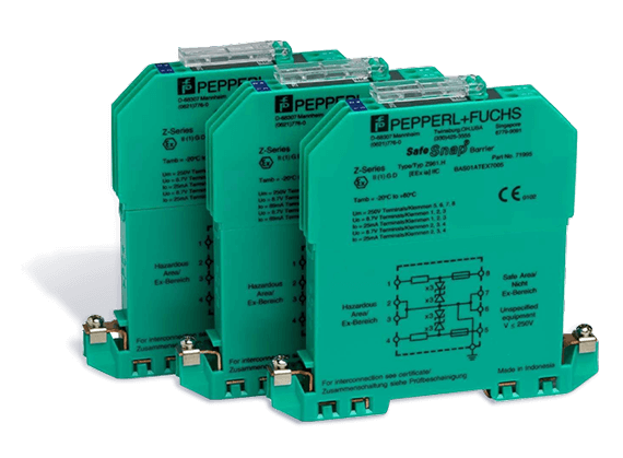
Each channel contains two stages of pulse-tested Zener or forward-. Z-system zener barriers from PepperlFuchs are directly mounted on. Bulletin 937TH Hazardous Location Switch Amplifiers with Safeguarding Devices Wiring Diagram 937TH-WD001.
Depending on the application increased or decreased intrinsic safety parameters apply for serial or parallel connection. A wiring diagram is a streamlined conventional photographic depiction of an electrical circuit. The anodes of the zener diodes are grounded.
To ensure the safety of such a wiring point T1 must be connected to ground as illustrated in Fig2. The barriers limit the el ectrical energy towards the ha zardous area by means of a combination of Zener diodes resistors and fuses. When Zener barriers are used they need to be considered in 2 modes.
7 WIRING INSTALLATION. Zener barriers have long been a cost-effective solution for providing an intrinsically safe interface with field devices located in the hazardous area. Zener Barrier Wiring Diagram DC.
Zener barrier wiring diagram d c. Our 937T Isolator Barriers include galvanic optical or transformer isolation. These barriers feature a narrow profile of just 125 mm to maximize control panel space.
The amount of energy transferred to the hazardous location is limited to a safe level incapable of igniting the explosive atmosphere. Zener Barrier Intrinsic Safety Modules are used in any application with Class 1 Division 1.
How Zener Barriers Work

How Zener Barriers Work

Zener Diode Barrier Principle Instrumentation Tools
Literature Rockwellautomation Com

048596 Pepperl Fuchs
Intrinsically Safe Explosion Proof For Pressure Sensor Zener Barrier Series Valcom Co Ltd Specialized Manufacturer Of Digital Pressure Meters And Load Cells

Zener Diode Barrier Principle Instrumentation Tools

Intrinsic Safety Explosion Proof Barrier Zener Barrier For Transducer Series Valcom Co Ltd Specialized Manufacturer Of Digital Pressure Meters And Load Cells

Extech Hazardous Area Specialist Products Supplier
Intrinsic Safety Engineering Eaton
Literature Rockwellautomation Com
Literature Rockwellautomation Com
Sd01a Zener Barrier Hbm
Literature Rockwellautomation Com

Safe Pak Relays And Zener Barriers Installation And Maintenance

How To Design An Intrinsically Safe System Awc Inc

Extech Hazardous Area Specialist Products Supplier
Stevenengineering Com

How Zener Barriers Work